The importance of a simple language
How the Kioko language uses Python as its main influence.
The 22nd of June 2026
From the mouse to the keyboard
For forty years, CAD has been a thing you do with a mouse: click a toolbar, drag a handle, fill a dialog, click OK. It works — but you can't diff a click, code-review a drag, or ask a colleague (or an AI) to read a thousand mouse gestures. So we made a deliberate pivot at Kioko, toward a coding interface: a model is a text file you write, read, version in Git, and generate with a language model. The geometry is the output of the program, not a binary blob locked inside a vendor's editor.
But tell a room of designers the future of CAD is code, and you can watch the room empty. And to be honest, that fear is a reasonable response to most of the code that has ever called itself CAD.
So we inherited the oldest question in programming — what should the language look like? — and for us it carried the whole project. If we were asking designers to leave the mouse and write their geometry, the language couldn't be one more wall; it had to be readable on the first try and writable by the afternoon. Making it simple wasn't a stylistic preference — it was the precondition for anyone using it at all. Get the language wrong and the most robust kernel in the world sits behind a door no designer will open.
A simple language, the Python way
When we designed the Kioko language, we took our cue not from CAD APIs but from Python — the language that won by being the one people could actually read. Python's bet was that code is read far more often than it is written, so clarity beats cleverness, and one obvious way to do a thing beats ten configurable ones.
We applied that bet to geometry. The whole Kioko language reduces to one pattern:
name = expression
A point is a name bound to an expression. So is a wing. So is the whole car. And the rule we hold above all others: one line creates one 3D object, carrying all the information that object needs — its type, its defining values, and its parents — and nothing more.
p0 = Point<Coordinates>(0, 0, 0)[reference]
Read it left to right and it tells you everything: a point named p0, defined by coordinates (0, 0, 0), anchored to the datum reference. The angle brackets say how the object is defined; the parentheses carry its values; the square brackets name its parents. One object, one line, complete.
We are not the first to decide CAD should be code. Four serious systems got there before us — and comparing them line for line is the clearest way to show why simplicity is the whole game.
The current code implementations
Each of these tools lets you describe geometry in text. They could hardly be more different in how.
- Siemens NXOpen — a programmatic API onto the NX kernel, in C#, C++, Java or Python. Anything the mouse can do, NXOpen can do — through sessions, builders and commits. You instantiate a builder, set its properties one at a time, commit it, then destroy it. The geometry is buried under object-lifecycle management.
- Onshape FeatureScript — a language purpose-built for parametric modelling, and the most elegant of the four. But it passes parameters as maps: every operation takes a JSON-style dictionary of key-value pairs, threaded with a
contextand anidyou manage by hand. - OpenCASCADE (OCCT) — the open-source C++ kernel behind much of the industry. Powerful and exact, but low-level: geometry is assembled from typed arrays, handles and builder classes, with topology (
TopoDS_*) layered on top of geometry (Geom_*). - OpenSCAD — a clean, functional CSG scripting language, beloved for 3D printing. Wonderfully simple — but built on primitives and boolean operations, with no concept of a free-form curve. There is no spline. There is no NURBS.
- Kioko —
name = expression. One declarative line per object.
The fastest way to feel the difference is to build the same thing in each. So let's build two: the simplest object there is, and a real one.
Example one — creating a point
A single point at the origin. Here is each language, verbatim in style.
NXOpen (.NET) — a session, a coordinate, a factory call:
Session theSession = Session.GetSession();
Part workPart = theSession.Parts.Work;
Point3d coordinates = new Point3d(0.0, 0.0, 0.0);
Point point = workPart.Points.CreatePoint(coordinates);
FeatureScript — a coordinate is a vector; the point entity is authored through the map-style sketch API:
var sketch1 = newSketch(context, id + "sketch1", {
    "sketchPlane" : qCreatedBy(makeId("Top"), EntityType.FACE)
});
skPoint(sketch1, "point1", { "position" : vector(0, 0) * meter });
skSolve(sketch1);
OpenCASCADE (C++) — a geometric point, then a topological vertex to make it real:
gp_Pnt aPnt(0.0, 0.0, 0.0);
TopoDS_Vertex aVertex = BRepBuilderAPI_MakeVertex(aPnt);
OpenSCAD — there is no point object at all; a coordinate is just a vector of data, and you can only see it by drawing something tiny there:
point = [0, 0, 0];          // data, not geometry
translate(point) sphere(0.1);
Kioko — the point itself is one complete line (the datum is reusable setup shared by everything):
reference = Datum<Reference>
p0 = Point<Coordinates>(0, 0, 0)[reference]
Example two — extruding a NURBS spline along an axis
Now a real piece of engineering geometry: a degree-3 NURBS curve through four control points, swept along an axis into a surface. This is the kind of operation aerodynamic surfacing is made of.
NXOpen (.NET) — the spline goes through a builder with a geometric constraint per point, then the extrude goes through a second builder with a section (abbreviated — the real thing is longer):
// --- build the degree-3 spline through 4 points ---
Features.StudioSplineBuilderEx splineBuilder =
    workPart.Features.CreateStudioSplineBuilderEx(nullFeature);
splineBuilder.DegreeValue = 3;
Point3d[] coords = {
    new Point3d(0, 0, 0), new Point3d(1, 2, 0),
    new Point3d(3, 2, 0), new Point3d(4, 0, 0)
};
foreach (Point3d c in coords) {
    Point pt = workPart.Points.CreatePoint(c);
    GeometricConstraintData gcd =
        splineBuilder.ConstraintManager.CreateGeometricConstraintData();
    gcd.Point = pt;
    splineBuilder.ConstraintManager.Append(gcd);
}
Features.Feature spline = splineBuilder.CommitFeature();
splineBuilder.Destroy();

// --- extrude the spline along Z ---
Section section = workPart.Sections.CreateSection(0.001, 0.001, 0.001);
// ... populate the section from the spline curve (several more lines) ...
Features.ExtrudeBuilder extrudeBuilder =
    workPart.Features.CreateExtrudeBuilder(nullFeature);
extrudeBuilder.Section = section;
extrudeBuilder.Direction = workPart.Directions.CreateDirection(
    new Point3d(0, 0, 0), new Vector3d(0, 0, 1),
    SmartObject.UpdateOption.WithinModeling);
extrudeBuilder.Limits.StartExtend.Value.RightHandSide = "0";
extrudeBuilder.Limits.EndExtend.Value.RightHandSide = "100";
Features.Feature extrude = extrudeBuilder.CommitFeature();
extrudeBuilder.Destroy();
FeatureScript — two map-style operations, one to fit the spline, one to extrude it:
opFitSpline(context, id + "spline1", {
    "points" : [
        vector(0, 0, 0), vector(1, 2, 0),
        vector(3, 2, 0), vector(4, 0, 0)
    ] * meter
});
opExtrude(context, id + "extrude1", {
    "entities" : qCreatedBy(id + "spline1", EntityType.EDGE),
    "direction" : vector(0, 0, 1),
    "endBound" : BoundingType.BLIND,
    "endDepth" : 100 * millimeter
});
OpenCASCADE (C++) — poles, knots and multiplicities assembled into typed arrays, then a curve, an edge and a prism:
// --- build a degree-3 NURBS curve from 4 poles ---
TColgp_Array1OfPnt poles(1, 4);
poles.SetValue(1, gp_Pnt(0, 0, 0));
poles.SetValue(2, gp_Pnt(1, 2, 0));
poles.SetValue(3, gp_Pnt(3, 2, 0));
poles.SetValue(4, gp_Pnt(4, 0, 0));

TColStd_Array1OfReal knots(1, 2);
knots.SetValue(1, 0.0);
knots.SetValue(2, 1.0);

TColStd_Array1OfInteger mults(1, 2);
mults.SetValue(1, 4);
mults.SetValue(2, 4);

Handle(Geom_BSplineCurve) curve =
    new Geom_BSplineCurve(poles, knots, mults, 3);

// --- turn it into an edge and extrude along Z ---
TopoDS_Edge edge = BRepBuilderAPI_MakeEdge(curve);
gp_Vec direction(0.0, 0.0, 100.0);
TopoDS_Shape prism = BRepPrimAPI_MakePrism(edge, direction);
OpenSCAD — it cannot be done. There is no NURBS in OpenSCAD. The closest you can get is sampling the curve into a straight-segment polygon yourself and extruding it, and even then linear_extrude only ever sweeps along Z, never an arbitrary axis:
// not a NURBS — a hand-made polyline, faceted, Z-axis only
pts = [[0, 0], [1, 2], [3, 2], [4, 0]];
linear_extrude(height = 100)
    polygon(points = pts);
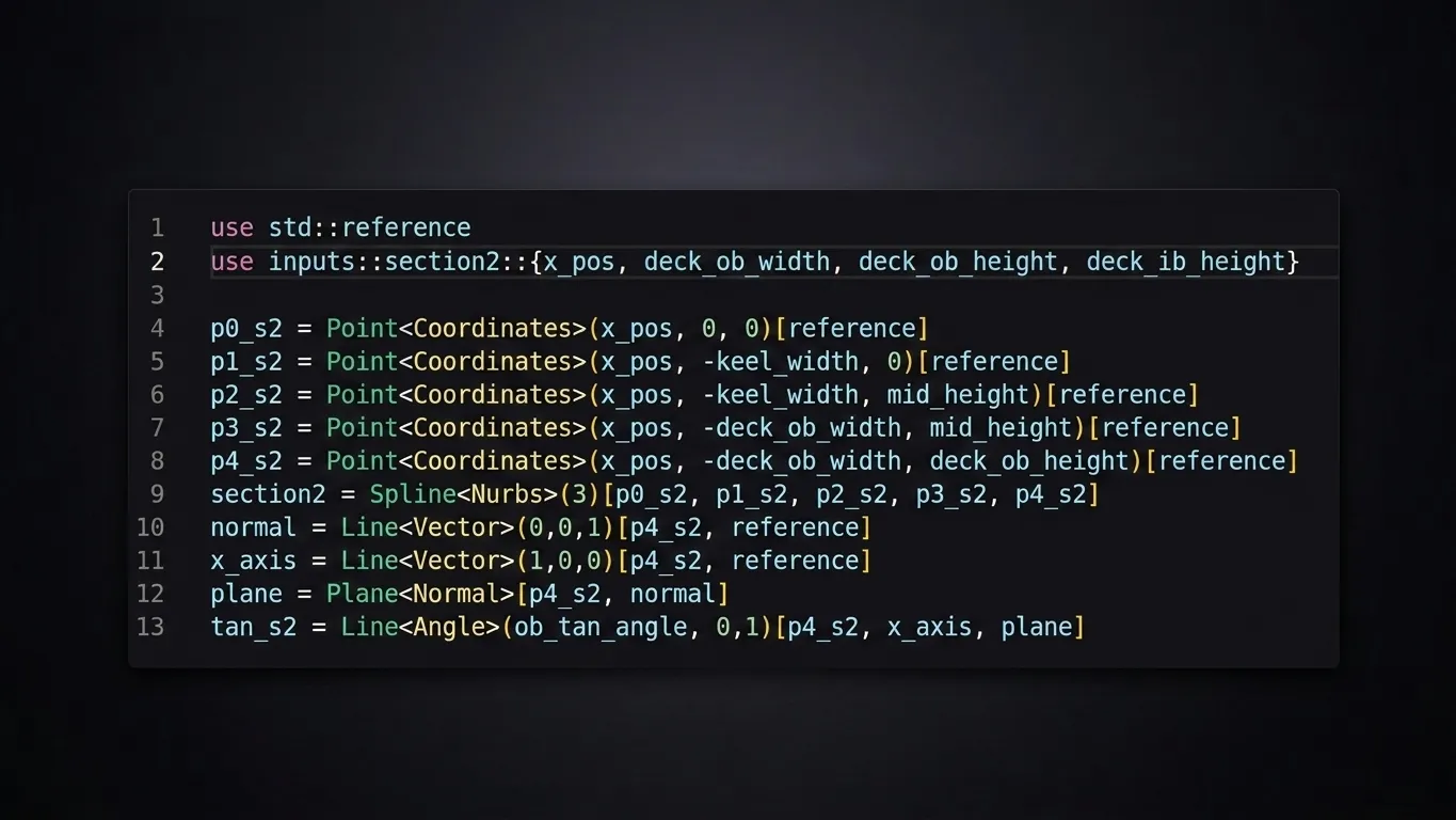
Kioko — the four control points, the curve, the axis, the surface — each one a complete line:
p0 = Point<Coordinates>(0, 0, 0)[reference]
p1 = Point<Coordinates>(1, 2, 0)[reference]
p2 = Point<Coordinates>(3, 2, 0)[reference]
p3 = Point<Coordinates>(4, 0, 0)[reference]
cubic = Spline<Nurbs>(3)[p0, p1, p2, p3]
axis  = Line<Vector>(0, 0, 100)[p0, reference]
wing  = Surface<Extrude>(0, 1)[cubic, axis]
How many lines for one object?
Lay the two examples side by side and the picture is hard to miss.
| API | Create a point | Extrude a NURBS along an axis |
|---|---|---|
| NXOpen (.NET) | 4 | ~28 |
| FeatureScript | 4 | ~14 |
| OpenCASCADE (C++) | 2 | ~18 |
| OpenSCAD | 1 (data only*) | not possible** |
| Kioko | 1 | 7 |
* OpenSCAD's "point" is a coordinate literal, not a geometric entity — there is no point object to select, reference or build on.
** OpenSCAD has no spline or NURBS primitive at all; the nearest workaround is a faceted polygon swept along the Z axis, which is neither a NURBS nor a free-axis extrusion.
The numbers tell the story the prose can only hint at. NXOpen needs the better part of thirty lines — sessions, builders, commits, destroys — to express one swept surface. OpenCASCADE is exact and powerful, but you assemble the NURBS by hand from arrays of poles, knots and multiplicities. FeatureScript is the most graceful of the established four, yet a single object still spreads across a dozen lines of dictionary. OpenSCAD is beautifully simple right up to the moment you need a real curve — and then it simply can't. Kioko expresses the same NURBS sweep — four control points and all — in seven lines, each a self-contained, readable statement of one object.
Why this matters
A one-line-per-object language isn't just tidier. It changes what you can do with the model.
- It disarms the fear we opened with. When a line reads
p0 = Point<Coordinates>(0, 0, 0), there is nothing to be afraid of — it says what it does, in the order you'd say it out loud. We've watched designers who swore they'd never write code become fluent in an afternoon. - It diffs and reviews like code. Change a wing section and version control shows one line changed — not a re-serialised binary or a fifty-key map. An engineer reads a Kioko file the way they read a pull request.
- It generates well. This matters most for where CAD is going, and it's no longer a hypothesis for us: when we trained language models on Kioko against the alternatives, the expressivity told. Because one line carries one complete object, the model learns a clean mapping from intent to geometry — none of the long-range bookkeeping of
context,idand half-finished builders that other APIs demand. The same prompt produces correct, valid Kioko far more often. A simple language isn't only kinder to the human reading it; it's measurably easier for a machine to write.
Simplicity is not cosmetic — it is what lets a language be read, shared, reviewed and now generated at scale. The mouse gave us geometry no one else could read. A simple language gives us geometry everyone — and everything — can.
Cherry on the cake: you don't have to choose
One last reassurance for anyone still holding a mouse: making the language this simple doesn't mean giving up the cursor. In Kioko the two interfaces are the same model. Click in the editor and you place a point the familiar way —
— but you can also just type the code, benefiting from intellisense. The same point is one line of text, and the scene updates in lockstep as you write it.
Two windows onto the same geometry — and you choose which one to use, moment to moment. That is what makes the leap to code safe: no one has to abandon the mouse to start writing geometry. They just gain a second way to express it — one that diffs, reviews, and generates.
If you'd like to build CAD that reads like Python, write to us at contact@kioko.io.